FEA Boundary Conditions
The main types of loading available in FEA include force, pressure and temperature. These can be applied to points, surfaces, edges, nodes and elements or remotely offset from a feature.
The way that the model is constrained can significantly affect the results and requires special consideration. Over or under constrained models can give stress that is so inaccurate that it is worthless to the engineer.
In an ideal world we could have massive assemblies of components all connected to each other with contact elements but this is beyond the budget and resource of most people. We can however, use the computing hardware we have available to its full potential and this means understanding how to apply realistic boundary conditions.
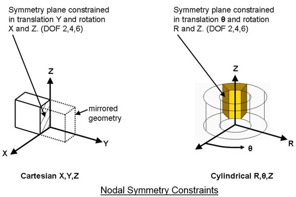
Symmetry Constraints
Symmetry constraints are useful in stabilizing models and reducing model size. You should not use symmetry constraints for non-symmetrical geometry unless you are sure that it will not affect the results. Two common types of nodal symmetry constraint are shown below for the Cartesian and Cylindrical coordinate system.
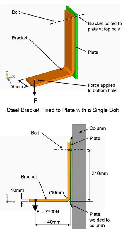
The Effects of Different Constraint Options
Consider a 50mm wide by 10mm thick ‘L’ shaped steel bracket as shown below. The bracket is bolted to a steel plate at the top hole and a load of 7500 N is applied to the bottom hole.
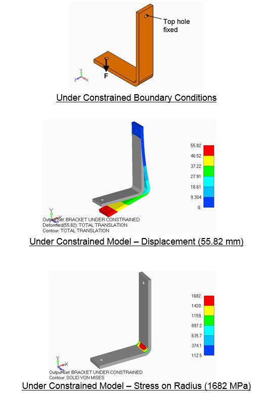
Under Constrained Model
This is an example of an under constrained model. The top hole is fixed and this allows the bracket to ‘penetrate’ the plate thus over estimating displacements.
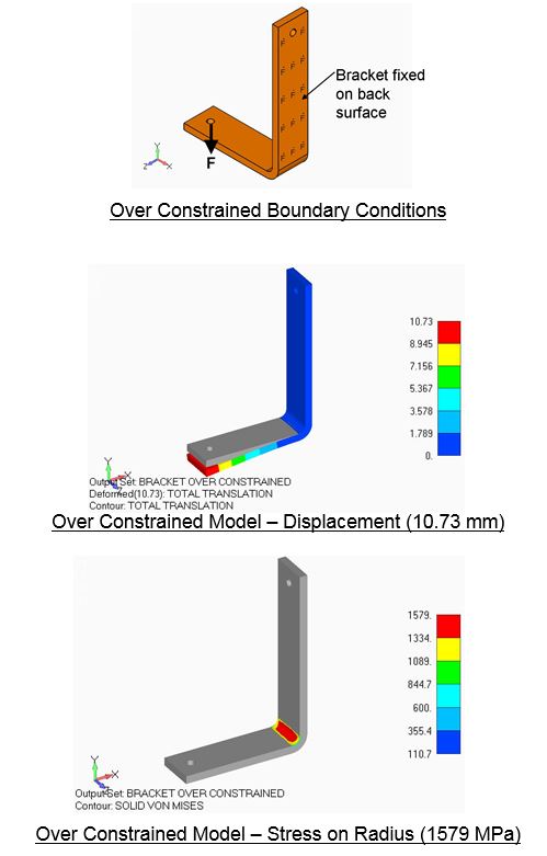
Over Constrained Model
This is an example of an over constrained model. The back face of the bracket is fixed. This prevents bending on the vertical part of the bracket thus under estimating the displacements.
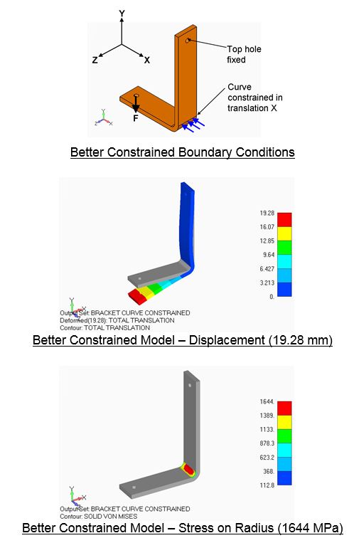
Better Constrained Model
This is a better way of constraining the model. The curve (line) at the edge of the back face radius is constrained horizontally in translation X and the top hole is fixed. This allows bending on the vertical part of the bracket and the displacement is more realistic.